 YouTube!
Kurzweil K1000 KXA Sound Block Installation Procedure
Very little of the content on this page is mine. My additions and comments are in red italics. This is a transcript of the official KXA Sound Block installation guide that I received from a dear friend along with an old K1000 I’m attempting to resurrect.
| KMS Part Number | Description | Location | Quantity |
|---|---|---|---|
| 12090001 | KXA Daughter Board | 1 | |
| 13003702 | Cable Assy | 1 | |
| 22008101 | Rubber Retainer Strip | 1 | |
| 82033007 | IC MEM 4M Sound ROM A00700X01 | U60/DGHTR | 1 |
| 82033008 | IC MEM 4M Sound ROM A00700Y01 | U52/DGHTR | 1 |
| 82033009 | IC MEM 4M Sound ROM A00700Z01 | U56/DGHTR | 1 |
| 82120005 | 1M EPROM KXA Set-up | U21/CPU | 1 |
| 82120006 | 1M EPROM KXA Set-up | U32/CPU | 1 |
| 91001201 | Warranty Card | 1 | |
| 91013802 | KXA Manual Addendum | 1 | |
| 91013902 | KXA Installation Procedure | 1 |
The following describes the necessary steps to install the K1000 KXA Sound Block. Please refer to the Static Sensitive Handling Procedure before beginning.
Although user programs are stored in RAM and may not be destroyed during this installation, user programs should be saved via the Kurzweil Object Mover program. If you do not have the Kurzweil Object Mover program available, inform the customer prior to performing this installation that you may need to perform a hard reset to the unity if problems occur and that his/her user programs will be erased.
- Turn off Power
- Remove phillips head screws from left (2) and right (3) endblocks.
- Remove (1) phillips head screw from the bottom of the unit located at the rear left hand side, next to the rubber foot (your left while standing at the keyboard).
- Remove (1) phillips head screw from the rear panel located on the left hand side closest to the bottom (your left while standing at the keyboard).
- Hold unit by endblocks and hinge top back into its service position.
- At this point you will see the following boards mounted on the bottom pan of the unit: CPU board, left; Keyboard Scan board, middle; Power Supply board, right.
- Remove the 8 phillips head screws underneath the unity which secure the keyboard to the chassis.
- Lift the keyboard slightly and disconnect the grey flat ribbon cable connected to the keyboard. If you have a K1000SE, disconnect the two-wire aftertouch lead from the motherboard.
- Once the keyboard is free, remove it and set it safely aside.
- Examine the short stranded cable supplied with this kit. You will be soldering the tinned wire end to an IC on the CPU board and connecting the other end to a connector on the KXA daughter board.
- Find location U49, you will be soldering the short cable to this IC. Solder the blue wire to Pin 13 of U49 and solder the red wire to Pin 12 of U49. It is not necessary to remove the CPU board to do this as you will be soldering on the component side of the board, however, please be sure you solder onto the leg of the IC.
- Remove U21 and U32 from the CPU board. Use extreme caution, these ICs need to be returned to Kurzweil in tact.
- Insert the new U21, part no. 82120005, and U32, part no. 82120006, provided with this kit. Be sure Pin 1 is facing the rear panel. CAUTION: Do not position the ICs by following the label direction. Position the ICs by following the notch or dot for Pin 1 only.
- Remove the ROMs in locations U50, U55 and U59 from the CPU board.
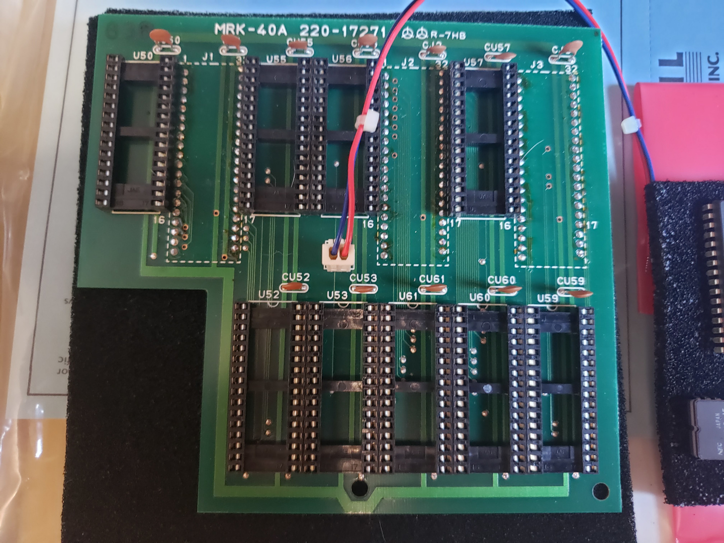
- Examine the KXA daughter board. You will notice the pins on the underside of the board. These pins insert into the U50, U55 and U59 sockets on the CPU board. You should line the board up as follows:
J1 on daughter board to U50
J2 on daughter board to U55
J3 on daughter board to U59 - Remove the adhesive backing from the nylon p.c. mounts on the KXA daughter board. In order for proper clearance for some parts on the CPU board, the p.c. mounts may need to be turned as you insert the daughter board.
- Because the daughter board will be flush with parts located on the CPU board, any capacitor that is standing straight up should be bent over prior to inserting the board.
- Insert the daughter boarding into the empty sockets carefully. If pins are bent, they may possibly break.
- Insert the connector end of the cable soldered to U49 to location P-CS on the daughter board. This connection is keyed, therefore, you will not be able to insert backwards.
- Insert the ROMs removed from locations U50, U55 and U59 on the CPU board into locations U50, U55 and U59 on the daughter board.
- Find locations U60, U52 and U56 on the daughter board. Insert ROMs received in packaged number 11007801 as follows:
Part number 82033007 in location U60
Part number 82033008 in location U52
Part number 82033009 in location U56
Be sure Pin 1 is facing the rear panel. CAUTION: Do not position the ICs by following the label direction. Position the ICs by following the notch for Pin 1 only. - Re-install the keyboard, connect the ribbon cable to the keyboard and place it in the chassis. It is not necessary at this time to install the keyboard mounting hardware.
- Put top cover back into operation position.
- Plug in unit and turn power on.
- Check unit for proper operation.
- If the unit is not working properly, power down and perform a hard reset. To do this, with the power off, hold down buttons labeled “A” and “B” simultaneously and turn the power on. Once LCD is lit, release the buttons and check for proper operation.
- If the unity is operating properly either initially or after the hard reset, power down. Hinge the top of the unity back into its service position. Take the rubber retainer strip supplied with this kit and remove the adhesive backing. This strip will be placed horizontal to the KXA daughter board. Place the strip on the inside rear panel of the unit. Be sure it is actually touching the daughter board to insure the board is secure. Next, return the top cover to normal operating position and insert all hardware removed.
- After the hardware is inserted, turn power on once more to check for proper operation prior to releasing the unit to the customer.
- Package ICs removed in the foam and antistatic bag that new ICs were received in and return them to Kurzweil as soon as possible. Please ship ICs via UPS standard, prepaid.
Date Installed:
Installed Where:
Customer Name:
Serial No. of Unit: