ORAC Wiring
The Machine End
The main wiring harness has 12 lines. Looking at the end of the harness that’s attached to the steppers and such, the connector is laid out like so:
| Thin Red + Yellow/White | Blue | Thick Black |
| Thin Yellow + Red/White | Green/Yellow | Thick Brown |
| Thin Orange + Black/White | Grey | Thick Red |
| Thin Black + Orange/White | Grey | Thick Orange |
The paired sets go to the carriage stepper and everything else goes out to the carriage itself.
Carriage Junction Box
Inside the junction box on the carriage, the four lines for the cross-slide stepper are broken out and the other four go off to the lamp and endstops.
| Thick Black | Thin Red + Yellow/White |
| Thick Brown | Thin Yellow + Red/White |
| Thick Red | Thin Orange + Black/White |
| Thick Orange | Thin Black + Orange/White |
| Grey (x2) | Endstops (NC) |
| Blue | Lamp Power |
| Green/Yellow | Lamp Ground |
Lamp
The lamp has a little toggle switch on the junction box at the base of the gooseneck and looks to be a standard mini bayonet socket. We’ll try out an LED and see how it goes.
Endstops
The endstops are a little bit interesting.
The cross-slide endstop switch is NO, but is held closed by a rod until the cross-slide is out to its end of motion. So far as I can tell, there in no mechanism to ensure that the cross-slide does not move too far in.
The carriage endstop switch is NC and is actuated by a rod in a movable holder clamped to the ways. As with the cross-slide, this mechanism only works in one direction. There is nothing to stop you from crashing the carriage into the tailstock.
The endstops are wired in series, so if either one opens, the whole circuit opens. This is great for reducing wiring, but less great in as much as you don’t know which endstop was triggered.
I’ll likely play around with these a bit in the future. If nothing else, adding positive endstops for safety.
Stepper Wiring
An 8-wire stepper conceptually looks like this:
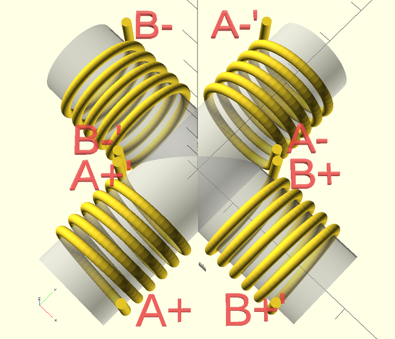
Each wire pair of a solid color and the same color with a white stripe are the two ends of a single winding. The wires with the white stripe are always the inside of the coil.
| Thin Red | A-‘ | Red/White | A- | |
| Thin Yellow | A+ | Yellow/White | A+’ | |
| Thin Orange | B- | Orange/White | B-‘ | |
| Thin Black | B+’ | Black/White | B+ |
From the connector and junction box, we know that some of our wires are connected together. Combining the two tables, we get:
| A-‘ | A+’ |
| A+ | A- |
| B- | B+ |
| B+’ | B-‘ |
Comparing this table to the wiring diagram above, we’re wired in bipolar-parallel mode. Parallel gets us better torque at higher speeds at the expense of lower stall torque and higher current draw.1 The steppers are rated for 90V and 3.1A per coil, which means 6.2A since we’re in parallel. At its best, a Smoothieboard can only deliver 2A and it only has 24V to get there with, so we’re quite a bit underpowered on that side. I don’t want to cut up the wiring harness, especially considering that parallel is better in the long run. If I wind up needing more than the Smoothie can give, I’ll just have to move up to external drives.
The Board End
It would be way too easy if the colors were all the same on the other side of the connector. Here’s the layout on the board side:
| Yellow | Orange | Black |
| Green | Green/Yellow | Brown |
| Blue | Grey | Red |
| Purple | Grey | Orange |
Combining the color/phase table with the layout table, we get:
| Carriage A-‘ and A+’ | Lamp Power | Cross-Slide A-‘ and A+’ |
| Carriage A+ and A- | Ground | Cross-Slide A+ and A- |
| Carriage B- and B+ | Endstop | Cross-Slide B- and B+ |
| Carriage B+’ and B-‘ | Endstop | Cross-Slide B+’ and B-‘ |
Putting it all together on the board connection side:
| Yellow | Carriage A-‘ and A+’ |
| Green | Carriage A+ and A- |
| Blue | Carriage B- and B+ |
| Purple | Carriage B+’ and B-‘ |
| Black | Cross-Slide A-‘ and A+’ |
| Brown | Cross-Slide A+ and A- |
| Red | Cross-Slide B- and B+ |
| Orange 2 | Cross-Slide B+’ and B-‘ |
| Orange 2 | Lamp Power |
| Green/Yellow | Ground |
| Grey 3 | Endstop |
| Grey 3 | Endstop |
Testing the board end wires for continuity, we find that Yellow & Green, Blue & Purple, Black & Brown, and Red & Orange are continuity pairs as we would expect given the above.
Footnotes
-
Mass Mind has a nice deep dive on stepper motor connection options. ↩
-
The oranges are not interchangeable and appear visually identical. Use a continuity tester at the wire end and the connector to make sure you’ve got the right one. ↩ ↩2
-
The greys are interchangeable since you’re just reading if the circuit is open or closed. ↩ ↩2