BLTouch, MKS SBASE v1.3, and OctoPrint
Wiring it up
The BLTouch has two sets of wires coming off of it with the following functions:
Servo Input
| Brown | Ground |
| Red | +5V |
| Orange | Servo Signal |
Switch Output
| Black | Ground |
| White | Switch Signal |
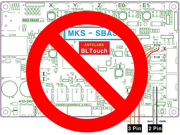
AntcLabs Wiring Does Not Work
I was really hoping that wiring would be as simple as AntcLabs shows. While this wiring using pin 1.24 should work in theory, it didn’t work for me in practice. Specifically, while the duty cycle updated appropriately, ping 1.24 would only give me ~0.5Vpp on the PWM signal.
If you’re going to try this method, make sure you have J4 (the jumper set right by the reset button) set to 5V.
Instead of troubleshooting deeply into why 1.24 didn’t work, I figured I’d just try 1.23 which worked exactly as it should, with 3.3Vpp.
Cutting it short
All in all, I was really not impressed with the BLTouch and I wound up going back to a only-when-needed mounted FSR on the nozzle. At some point I may try the BLTouch again, but right now I don’t see a good reason. If I do, I’ll finish this post. If not, I won’t.