Motor Control with DROK ZS-H3 and Raspberry Pi
Parts
You of course don’t need to use exactly the same equipment I’m using, but for full transparency (and Amazon referral links to help cover hosting costs), here’s the bill of materials to replicate my setup exactly.
- 30V 5A Bench Power Supply
- LM2596 Buck Converter
- ZS-H3 DC Motor Control (Spec Sheet)
- Generic 12V Motor
- Assorted Jumper Wires
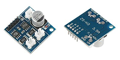
The Motor Controller
The ZS-H3 is a cheap little dual DC motor driver with impressive stats for its size and cost. It can handle 7.5-40V for motor drive, sustaining 2.5A per channel and peaking at 3.5A per channel. My eventual plan is to use this to drive the impeller and traction motors on my hacked up Maytronics Dolphin. Hopefully the peak current is enough since space is at a premium in the water-tight control box and I haven’t found anything else that can handle 30V and several amps in this small of a form-factor. At any rate, let’s not get bogged down in that project just yet. For today, I just want to show how to connect the motor drive to a Raspberry Pi and do some simple control with python.
Wiring Up
With all credit to WiringPi, here’s what the pinout of the Raspberry Pi looks like if you stand it up with the ethernet and USB jacks on the bottom:
| BCM | wPi | Name | Mode | V | Phy | Phy | V | Mode | Name | wPi | BCM |
|---|---|---|---|---|---|---|---|---|---|---|---|
| 3.3v | 1 | 2 | 5v | ||||||||
| 2 | 8 | SDA.1 | IN | 1 | 3 | 4 | 5v | ||||
| 3 | 9 | SCL.1 | IN | 1 | 5 | 6 | 0v | ||||
| 4 | 7 | GPIO. 7 | IN | 1 | 7 | 8 | 0 | IN | TxD | 15 | 14 |
| 0v | 9 | 10 | 1 | IN | RxD | 16 | 15 | ||||
| 17 | 0 | GPIO. 0 | IN | 0 | 11 | 12 | 0 | IN | GPIO. 1 | 1 | 18 |
| 27 | 2 | GPIO. 2 | IN | 0 | 13 | 14 | 0v | ||||
| 22 | 3 | GPIO. 3 | IN | 0 | 15 | 16 | 0 | IN | GPIO. 4 | 4 | 23 |
| 3.3v | 17 | 18 | 0 | IN | GPIO. 5 | 5 | 24 | ||||
| 10 | 12 | MOSI | IN | 0 | 19 | 20 | 0v | ||||
| 9 | 13 | MISO | IN | 0 | 21 | 22 | 0 | IN | GPIO. 6 | 6 | 25 |
| 11 | 14 | SCLK | IN | 0 | 23 | 24 | 1 | IN | CE0 | 10 | 8 |
| 0v | 25 | 26 | 1 | IN | CE1 | 11 | 7 | ||||
| 0 | 30 | SDA.0 | IN | 1 | 27 | 28 | 1 | IN | SCL.0 | 31 | 1 |
| 5 | 21 | GPIO.21 | IN | 1 | 29 | 30 | 0v | ||||
| 6 | 22 | GPIO.22 | IN | 1 | 31 | 32 | 0 | IN | GPIO.26 | 26 | 12 |
| 13 | 23 | GPIO.23 | IN | 0 | 33 | 34 | 0v | ||||
| 19 | 24 | GPIO.24 | IN | 0 | 35 | 36 | 0 | IN | GPIO.27 | 27 | 16 |
| 26 | 25 | GPIO.25 | IN | 0 | 37 | 38 | 0 | IN | GPIO.28 | 28 | 20 |
| 0v | 39 | 40 | 0 | IN | GPIO.29 | 29 | 21 |
For this project, I’ve set my bench supply to 12V, which is the motor drive voltage. To power the Pi, I’m using the buck converter to tap 5V off of the main supply. If you’re just playing around on your bench, you can power the Pi any way you like. I’m doing it this way as once I shove this all into the Dolphin, my only power source is 30V.
| Buck Converter | Raspberry Pi Physical Pin |
|---|---|
| +5V | 4 |
| Ground | 6 |
The ZS-H3 pinout is a little simpler:
| Pin | Description |
|---|---|
| A2 | Counter-Clockwise Input for Motor A |
| A1 | Clockwise Input for Motor A |
| B2 | Counter-Clockwise Input for Motor B |
| B1 | Clockwise Input for Motor B |
| GND | Ground |
To drive the motors, just send a PWM signal on the pin for the motor and direction you want to go. The duty cycle of the PWM signal should be proportional to the speed you want the motor to go.
If you light up both the CW and CCW pins of a single motor at the same time, the controller will act as an electric brake.
The ZS-H3 can officially read control PWM signal ranging from 500Hz-30KHz, but it appears to handle anything lower as well. So far as I can tell, the ZS-H3 does not intelligently set a voltage level output to the motor based on the PWM input. Rather, it toggles the full motor output voltage on and off following the PWM signal.
Connecting the ZS-H3 to the Pi:
| ZS-H3 | Raspberry Pi Physical Pin |
|---|---|
| B2 | 11 |
| B1 | 16 |
| GND | 14 |
Software
Once you’re wired up, you can play around with WiringPi’s gpio on the command line, but dorking around with python is more valuable for my Dolphin project, so that’s the route I went:
#!/usr/bin/python

import time

import RPi.GPIO as GPIO
GPIO.setmode(GPIO.BOARD)

cw = 16
ccw = 11
frequency = 50

direction = cw

GPIO.setup(cw, GPIO.OUT)
GPIO.setup(ccw, GPIO.OUT)

pwm = GPIO.PWM(direction, frequency)
pwm.start(10)


while True:
    speed = input("Speed? (0-100) ")
    if speed == 0:
        pwm.stop()
        if direction == cw:
            direction = ccw
        else:
            direction = cw
        pwm = GPIO.PWM(direction, frequency)
        time.sleep(1)
        pwm.start(10)
    else:
        pwm.ChangeDutyCycle(speed)
This little script prompts you for a speed (0-100%) and starts Motor B spinning at that speed. If you give a speed of 0, it stops the motor, waits a second to make sure the motor stops and we don’t get any interesting back-current effects, reverses direction, then starts up slowly in the other direction.