 YouTube!
Kurzweil K1000SE Components
Table of Contents
Headers & Harnesses
Diagrams created with WireViz.
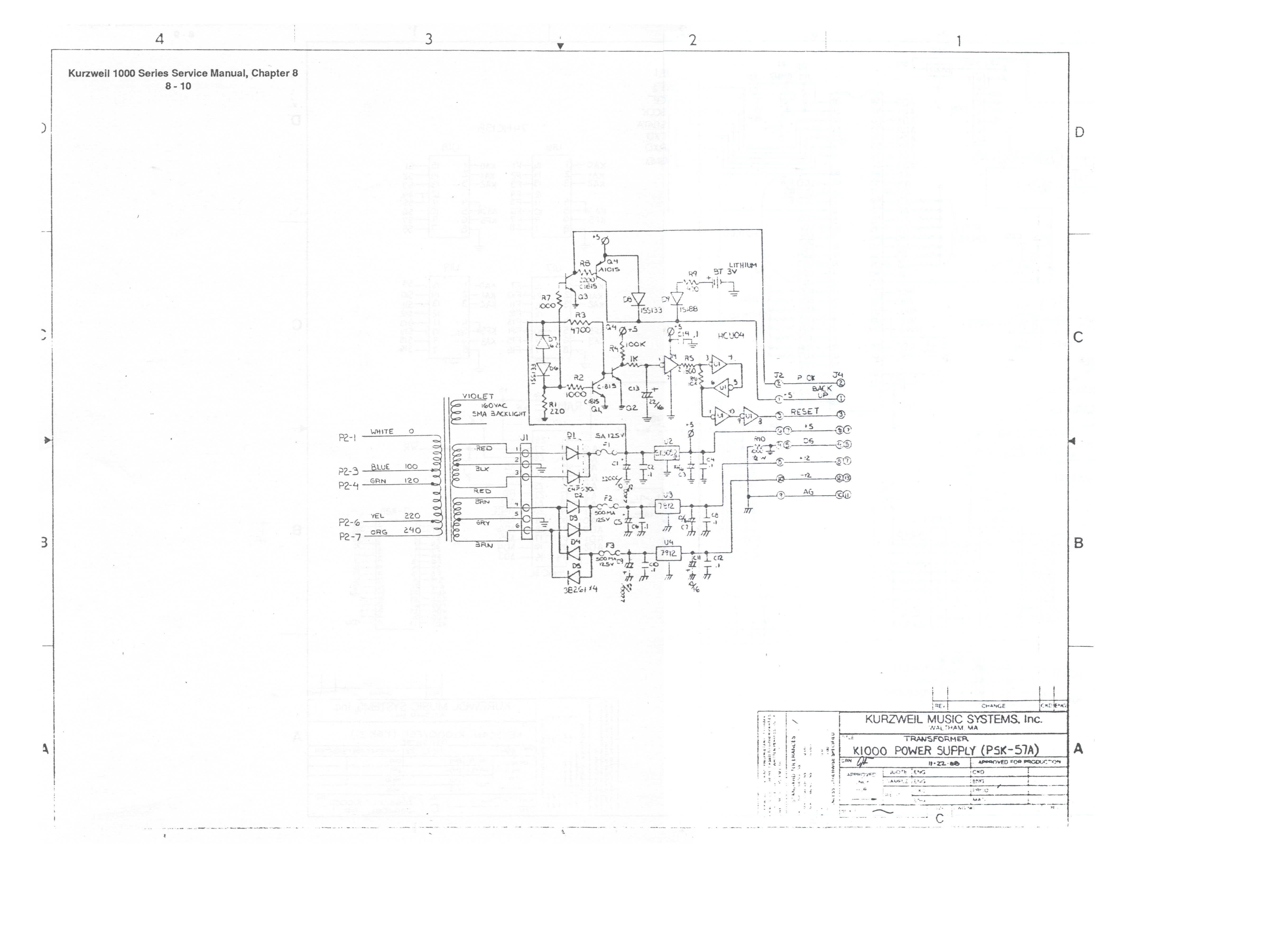
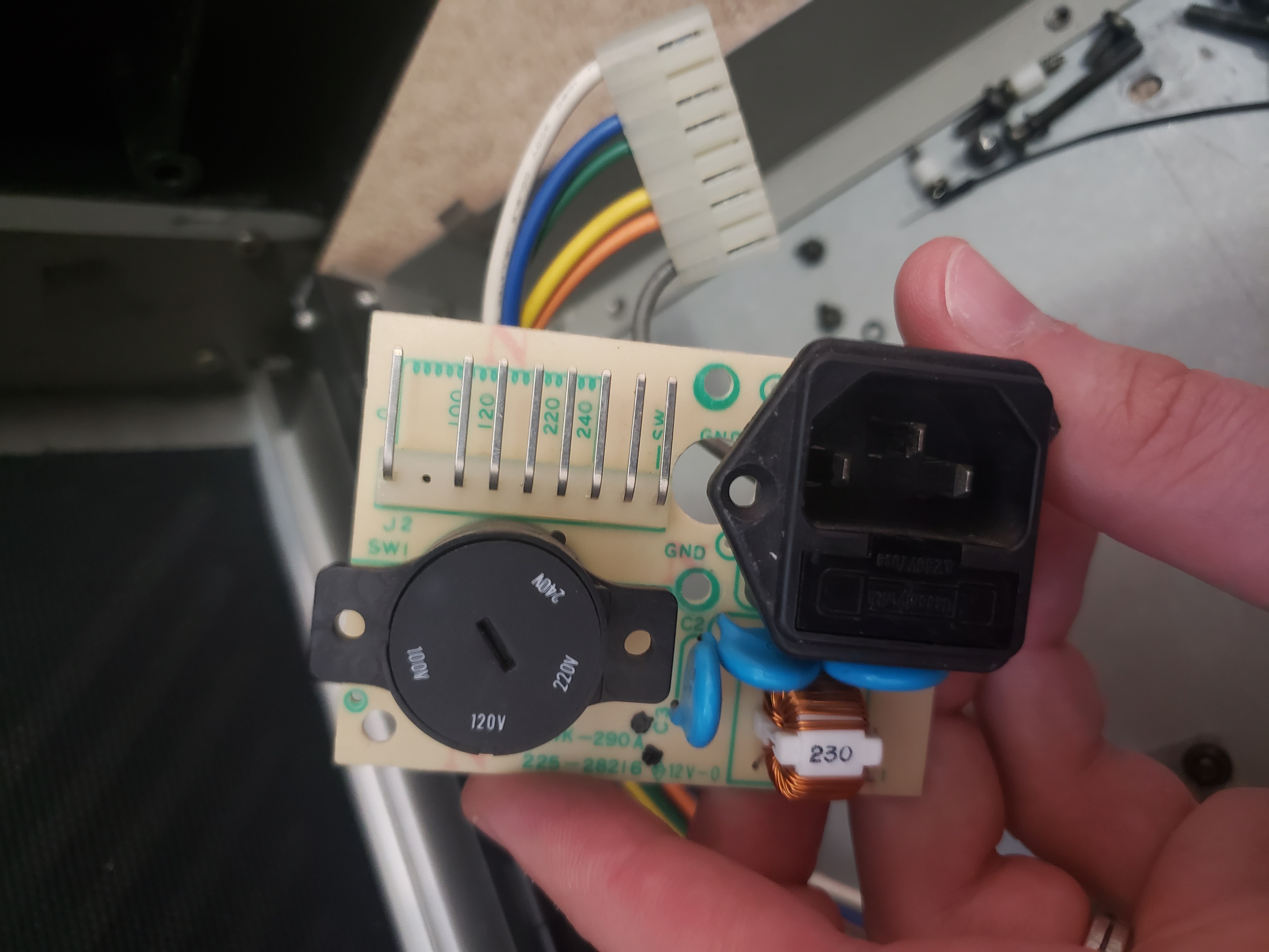
Power Block <-> Transformer

connectors:
   Power Block Mains:
      pinout: [Hot, Neutral]
   Power Block J2:
      pinout: [P2-1, P2-2, P2-3, P2-4, P2-5, P2-6, P2-7, P2-8, P2-9]
   Transformer:
      pinout: [GND, 100Vac, 120Vac, 220Vac, 240Vac]
   Power Switch:
      pinout: [A, B]
   Voltage Selector:
      pinout: [100Vac, 120Vac, 220Vac, 240Vac, Input]

cables:
   W1:
      colors: [WH, BU, GN, YE, OG]
   Power Block Traces:
      colors: [BU, GN, YE, OG]
   Power Block Trace:
      colors: [BK]
   W2:
      colors: [GY,BN]

connections:
   -
      - Transformer: [1,2,3,4,5]
      - W1: [1-5]
      - Power Block J2: [1,3,4,6,7]
   -
      - Voltage Selector: [1-4]
      - Power Block Traces: [1-4]
      - Power Block J2: [3,4,6,7]
   -
      - Voltage Selector: [5]
      - Power Block Trace: [1]
      - Power Block Mains: [1]
   -
      - Power Switch: [1]
      - W2: [1]
      - Power Block J2: [9]
   -
      - Power Switch: [2]
      - W2: [2]
      - Power Block Mains: [2]
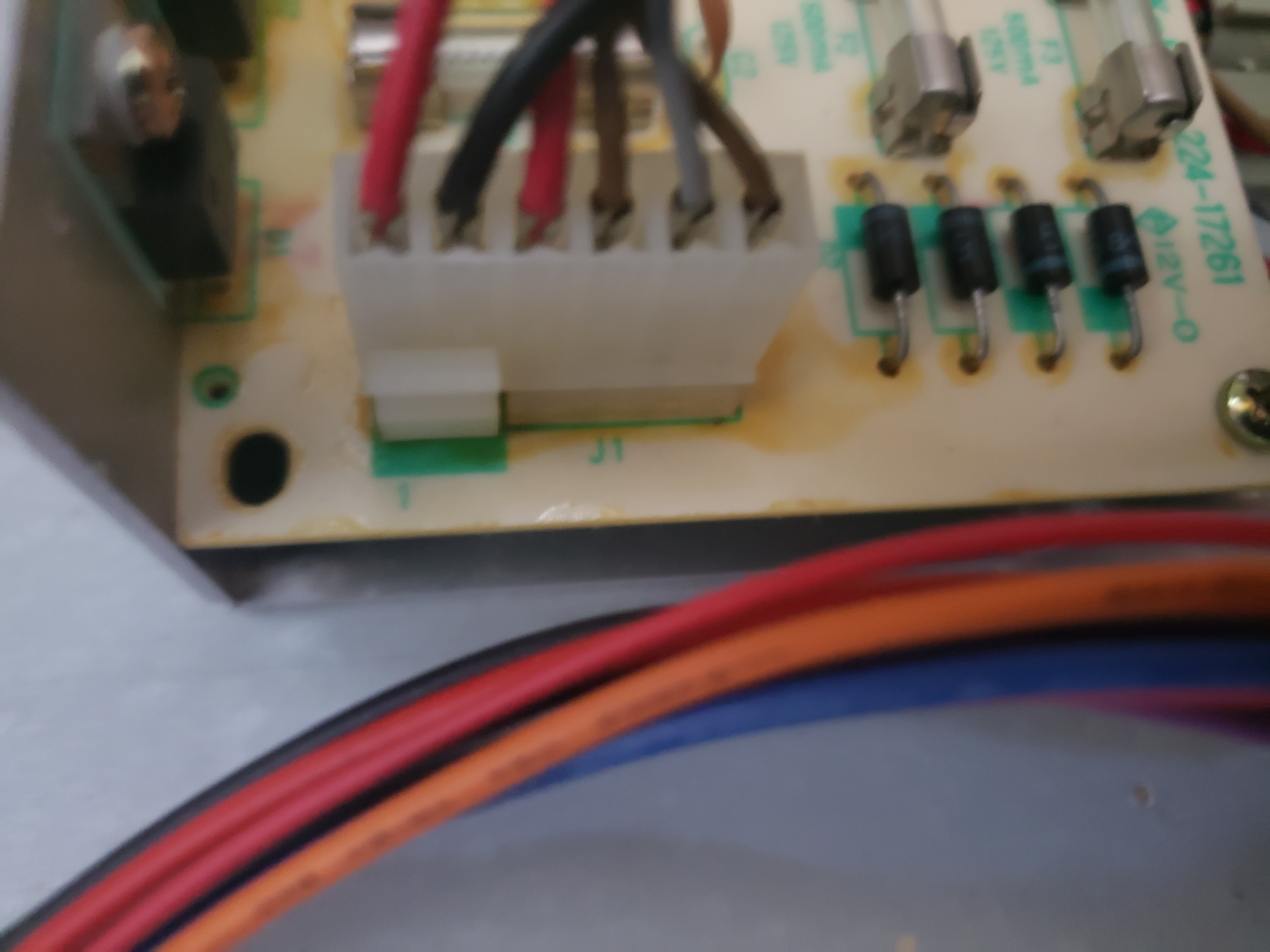
Transformer <-> PSU

connectors:
   Transformer:
      pinout: [5Vac, GND, 5Vac, 12Vac, GND, 12Vac]
   PSU J1:
      pinout: [5Vac, GND, 5Vac, 12Vac, GND, 12Vac]

cables:
   W1:
      colors: [RD, BK, RD, BN, GY, BN]

connections:
   -
      - PSU J1: [1-6]
      - W1: [1-6]
      - Transformer: [1-6]
PSU <-> Audio Controls
PSU Schematic |
Volume Slider Schematic

connectors:
   PSU J4:
      pinout: [' ', ' ', ' ', GND, GND, +5Vdc, +5Vdc, -12Vdc, +12Vdc, ' ', GND, ' ', -12Vdc]
   Audio Board J-PS:
      pinout: [+5Vdc, +5Vdc, GND, GND, ' ']
   Audio Board J-AN:
      pinout: [3.2Vdc, 3.2Vdc, AN0 (Pitch Bender Signal), AN1 (Mod Wheel Signal), AN2 (Data Slider Signal), AN3, GND, GND]
   Main Board J15:
      pinout: [' ', ' ', ' ', GND]
   Volume Slider J2:
      pinout: [GND, RIGHT, LEFT, GND, -12Vdc, +12Vdc]
   Headphone Jack:
      pinout: [SLEEVE, TIP, RING]
   Input Wheels Junction:
      pinout: [-12Vdc, 'Pitch Bender Signal', 'Mod Wheel Signal',' ',' ']
   Mod Wheel:
      pinout: [-12Vdc, WIPER, ' ']
   Pitch Bender:
      pinout: [-12Vdc, WIPER, ' ']
   Data Slider:
      pinout: [3.2Vdc, WIPER, GND]

cables:
   Audio Board Power:
      colors: [RD, RD, BK, BK]
   Data Slider Pigtail:
      colors: [OG, BU, BK]
   Headphone Output:
      colors: [BK, RD, WH]
   Input Wheels:
      colors: [BN, YE]
   Input Wheels Power/Reference (+) - UNCONFIRMED:
      colors: [BK]
   Input Wheels Power/Reference (-):
      colors: [OG]
   Main Board J15 Pigtail:
      colors: [WH, BK]
   Mod Wheel Pigtail:
      colors: [BU, YE, RD]
   Pitch Bender Pigtail:
      colors: [BU, GN, RD]
   Volume Slider Power/Reference:
      colors: [BK, VT, BU]

connections:
   -
      - Audio Board J-PS: [1-4]
      - Audio Board Power: [1-4]
      - PSU J4: [7,6,5,4]
   -
      - Volume Slider J2: [4-6]
      - Volume Slider Power/Reference: [1-3]
      - PSU J4: [11,13,9]
   -
      - Volume Slider J2: [1-3]
      - Headphone Output: [1-3]
      - Headphone Jack: [1-3]
   -
      - Main Board J15: [1,4]
      - Main Board J15 Pigtail: [1,2]
      - Audio Board J-AN: [6,7]
   -
      - Input Wheels Junction: [5]
      - Input Wheels Power/Reference (+) - UNCONFIRMED: [1]
      - Main Board J15: [3]
   -
      - Input Wheels Junction: [1]
      - Input Wheels Power/Reference (-): [1]
      - PSU J4: [8]
   -
      - Pitch Bender: [1-3]
      - Pitch Bender Pigtail: [1-3]
      - Input Wheels Junction: [1,2,5]
   -
      - Mod Wheel: [1-3]
      - Mod Wheel Pigtail: [1-3]
      - Input Wheels Junction: [1,3,5]
   -
      - Input Wheels Junction: [2,3]
      - Input Wheels: [1,2]
      - Audio Board J-AN: [3,4]
   -
      - Data Slider: [1-3]
      - Data Slider Pigtail: [1-3]
      - Audio Board J-AN: [2,5,8]
PSU <-> CPU

connectors:
   PSU J2:
      pinout: [+5V (Backup), PCK, RESET, GND (Digital), GND (Digital), +5V, +5V, +12V, GND (Analog), -12V]
   CPU J4:
      pinout: [GND (Digital), GND (Digital), +5V, +12V, -12V, GND (Analog), +5V (Backup), +5V, PCK, RESET]

cables:
   W1:
      wirecount: 10
      colors: [BK, BK, RD, BU, OG, BK, RD, RD, VT, YE]

connections:
   -
      - CPU J4: [1-10]
      - W1: [1-10]
      - PSU J2: [4,5,6,8,10,9,1,7,2,3]
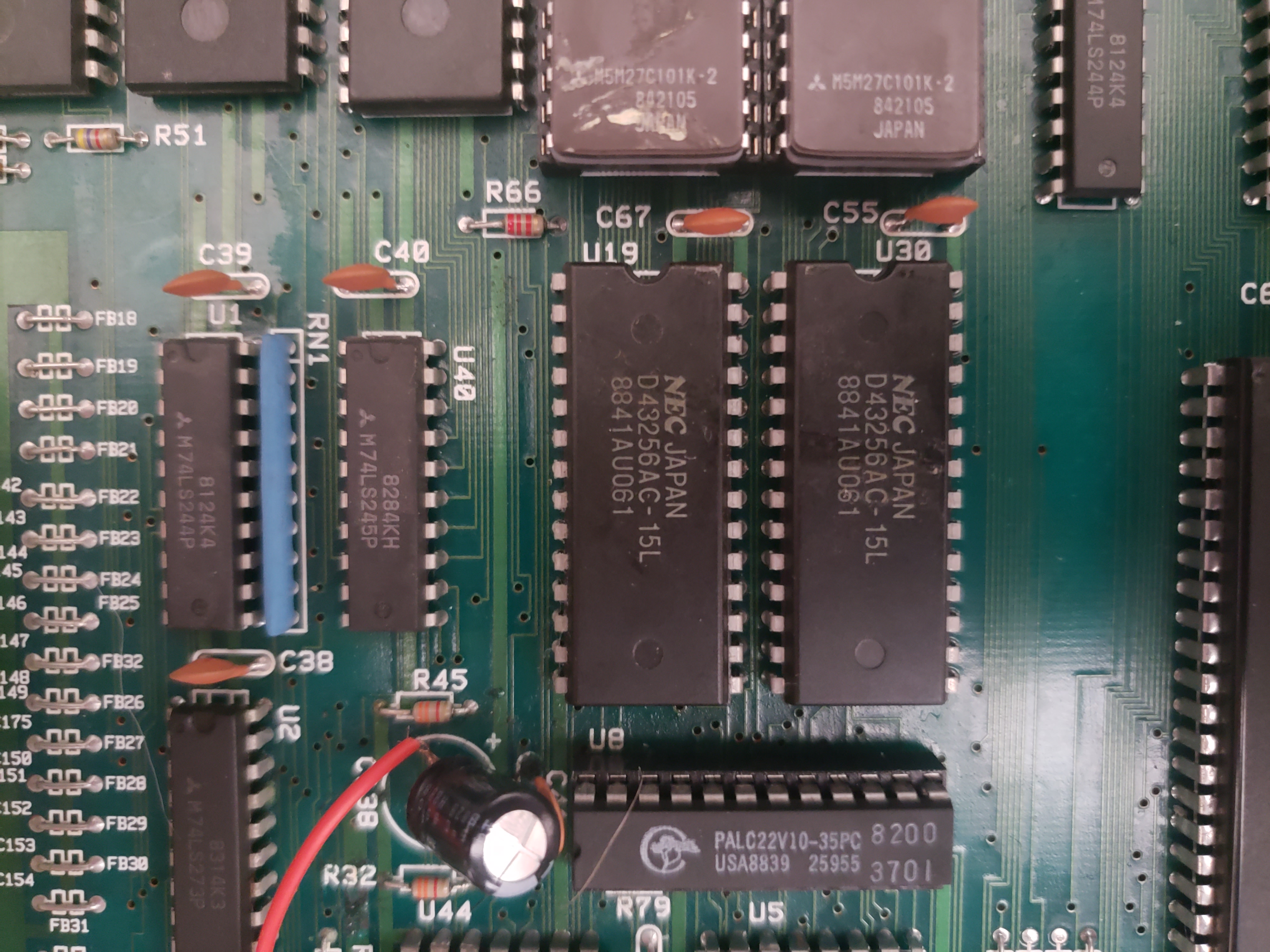
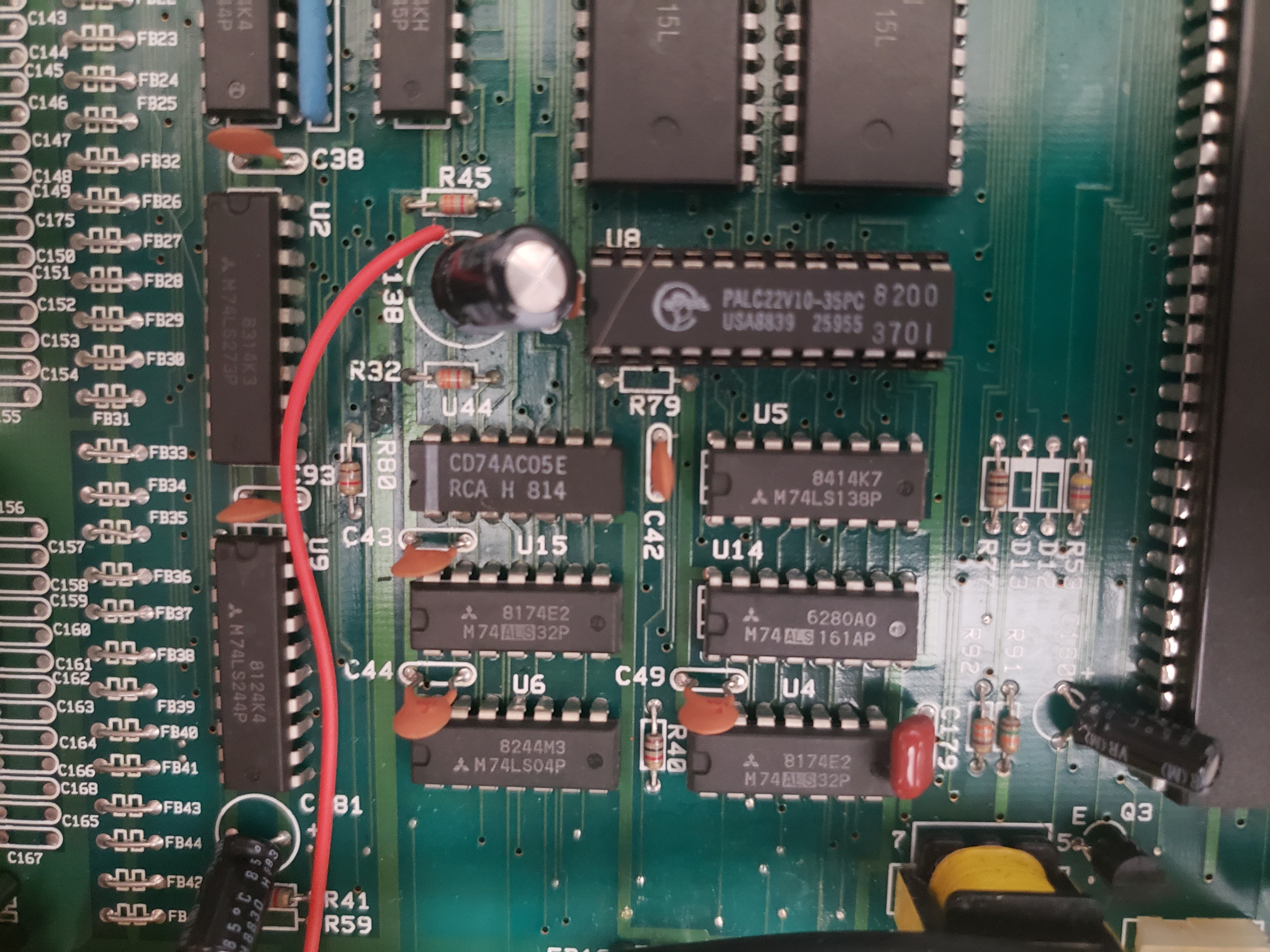
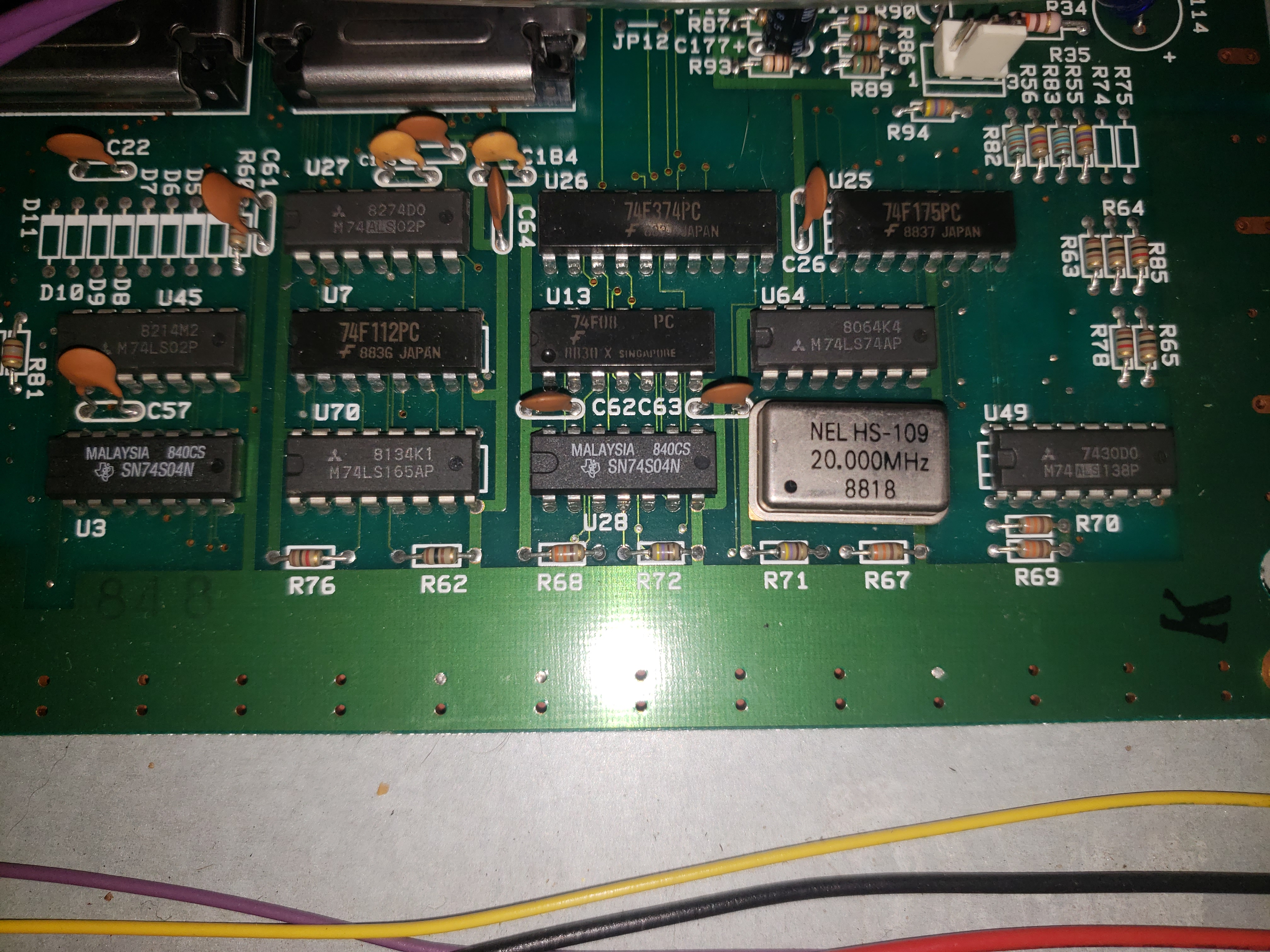
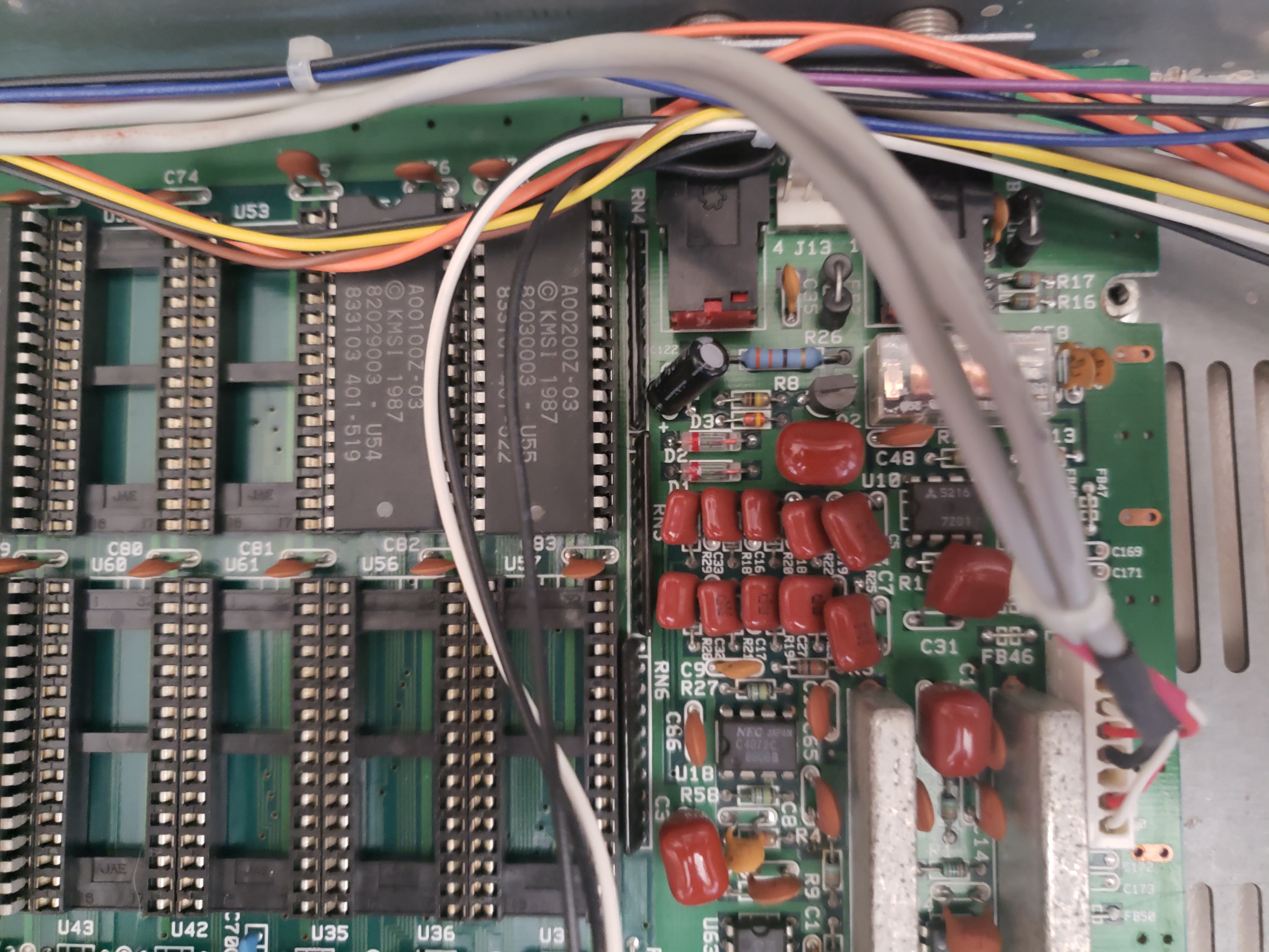
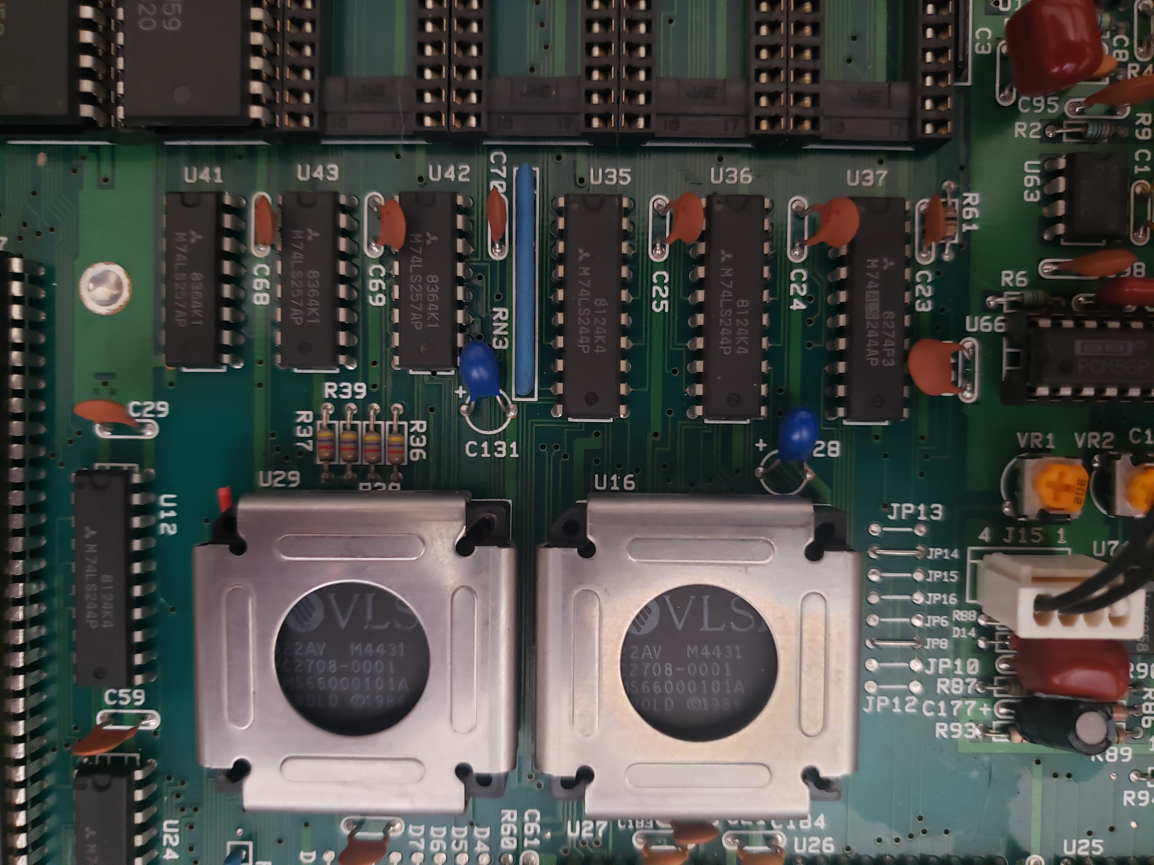
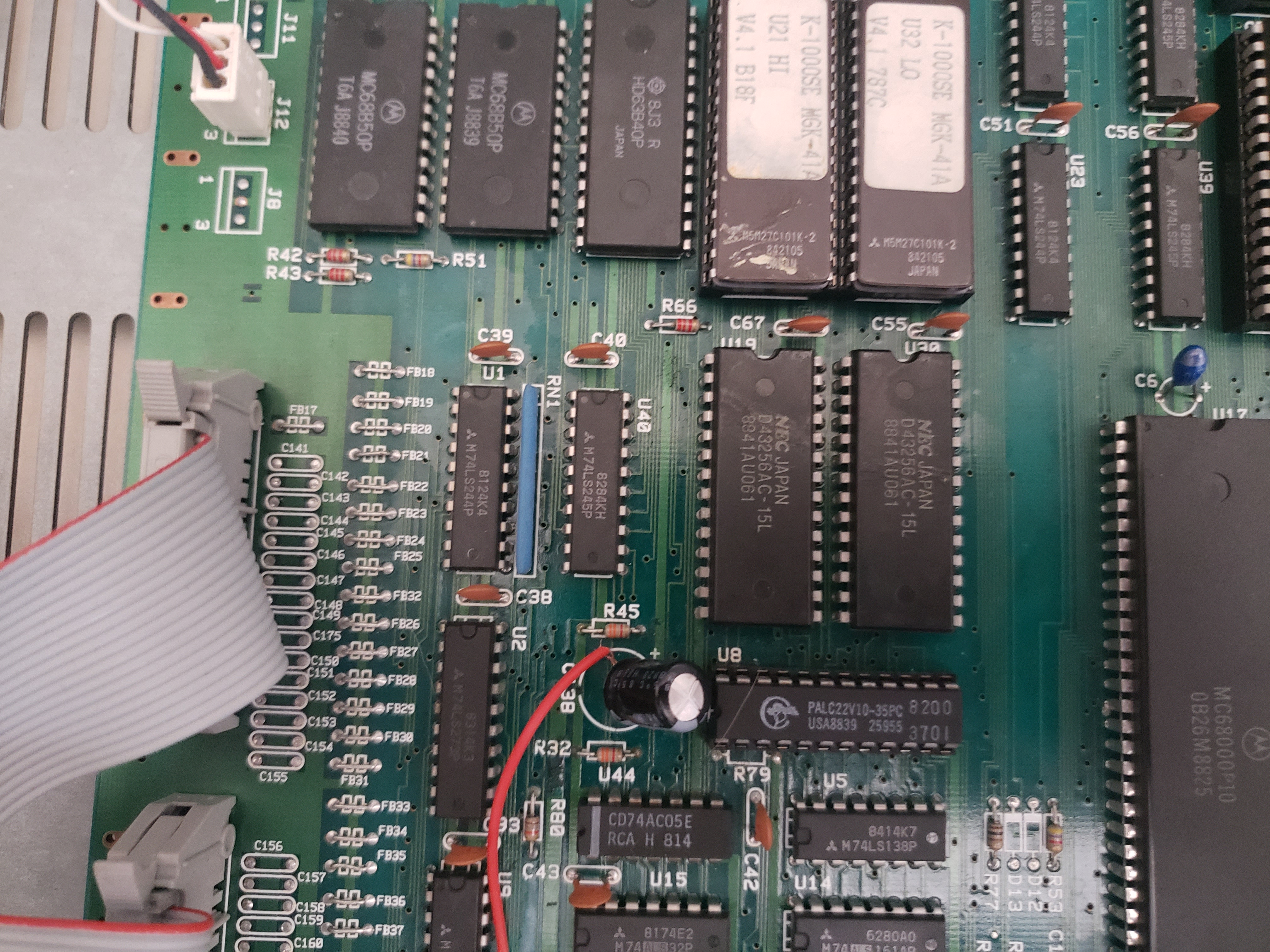
Chips
| Position | Part Number | Description | Mount | Picture |
|---|---|---|---|---|
| U1 | M74LS244P | Octal Buffer / Line Driver | Fixed | Picture |
| U2 | M74LS273P | Octal Flip Flop | Fixed | Picture |
| U3 | SN74S04N | Hex Inverters | Fixed | Picture |
| U4 | M74ALS32P | Quad 2-Input Positive OR Gates | Fixed | Picture |
| U5 | M74LS138P | 3-to-8 Decoder / Demultiplexer | Fixed | Picture |
| U6 | M74LS04P | Hex Inverters | Fixed | Picture |
| U7 | 74F112PC | Dual JK LE Flip Flop | Fixed | Picture |
| U8 | PALC22V10-35PC | CMOS Programmable Array Logic | Socket | Picture |
| U9 | M74LS244P | Octal Buffer / Line Driver | Fixed | Picture |
| U10 | M5216 | Dual Op-Amp | Fixed | Picture |
| U11 | M74LS244P | Octal Buffer / Line Driver | Fixed | |
| U12 | M74LS244P | Octal Buffer / Line Driver | Fixed | Picture |
| U13 | 74F08PC | Quad 2-Input AND Gate | Fixed | Picture |
| U14 | M74ALS151AP | 1-of-8 Data Selector / Multiplexer | Fixed | Picture |
| U15 | M74ALS32P | Quad 2-Input Positive OR Gates | Fixed | Picture |
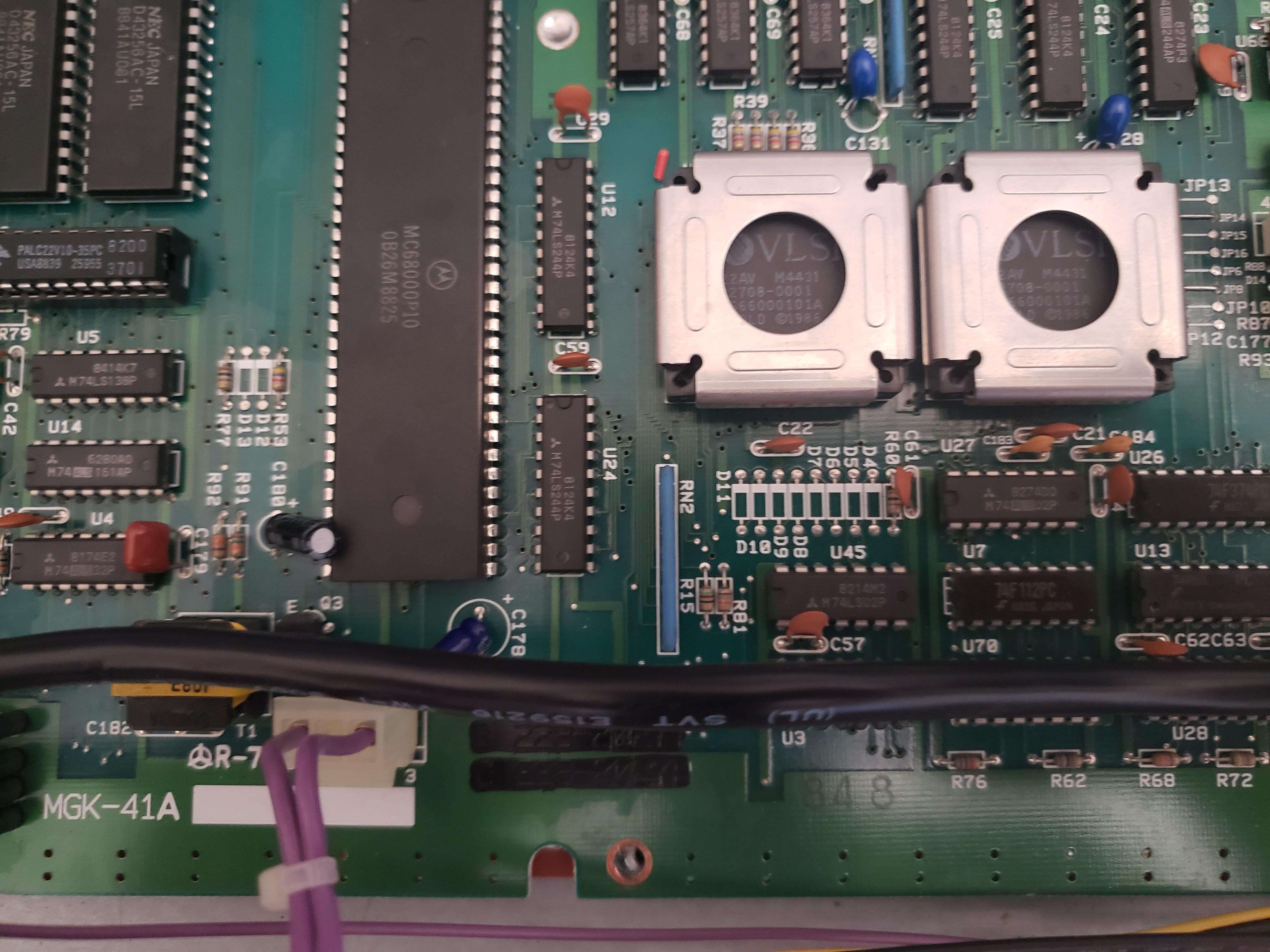
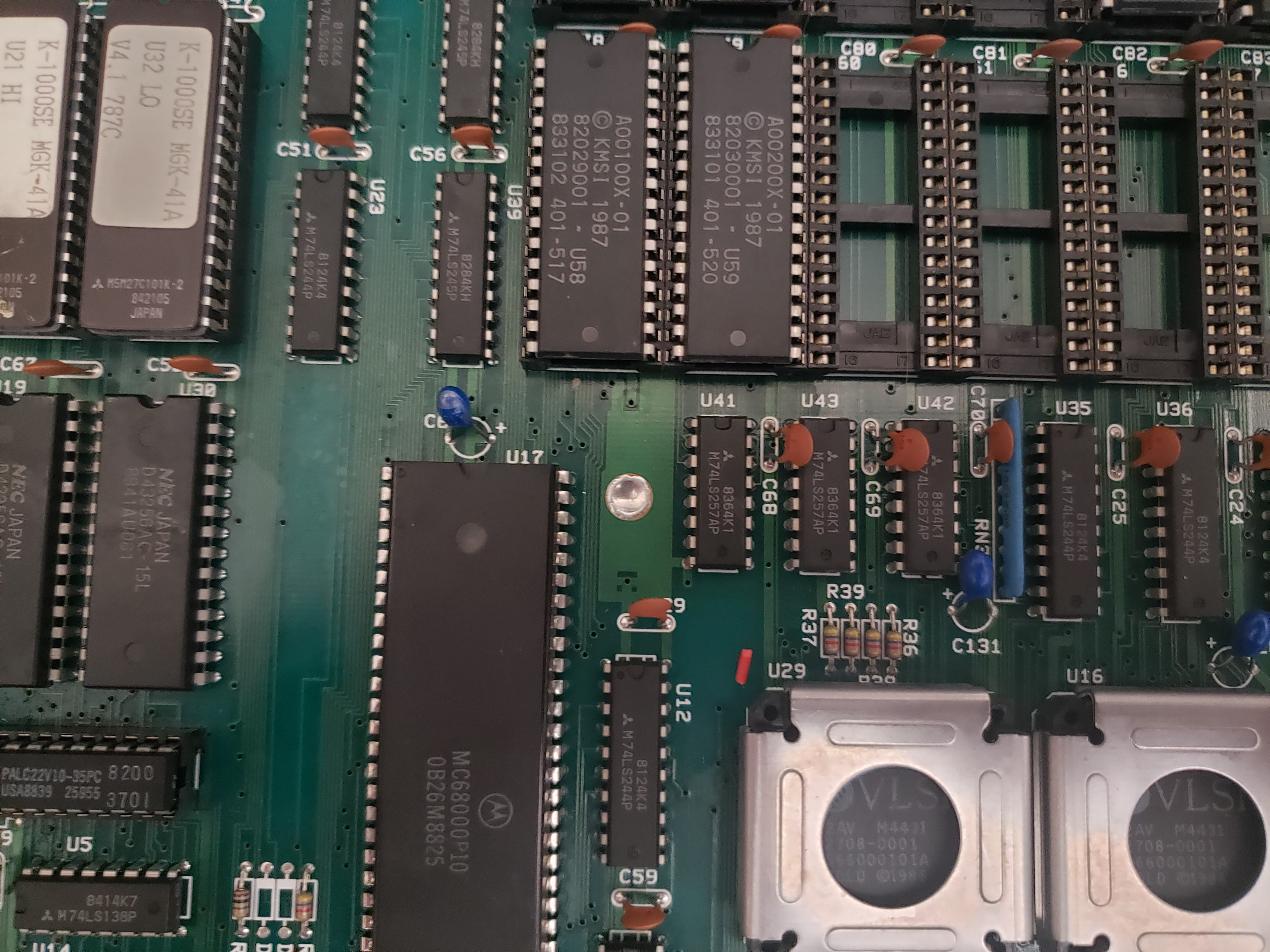
| U16 | KMS66000101A | Arnold Chip (KMS Proprietary?) | Socket | Picture |
| U17 | MC68000P10 | 10MHz CPU | Fixed | |
| U18 | C4072C | J-FET Input Dual Op-Amp | Fixed | Picture |
| U19 | D43256AC-15L | 32K RAM | Fixed | Picture |
| U20 | ||||
| U21 | M5M27C101K-2 | Software Engine EPROM (HI) | Socket | |
| U22 | ||||
| U23 | M74LS244P | Octal Buffer / Line Driver | Fixed | Picture |
| U24 | M74LS244P | Octal Buffer / Line Driver | Fixed | Picture |
| U25 | 74F175PC | Quad D-Type Flip-Flop | Fixed | Picture |
| U26 | 74F374PC | Octal D-Type Flip-Flop with 3-STATE Outputs | Fixed | Picture |
| U27 | M74ALS02P | Quad 2-Input Positive NOR Gate | Fixed | Picture |
| U28 | SN74S04N | Hex Inverters | Fixed | Picture |
| U29 | KMS66000101A | Arnold Chip (KMS Proprietary?) | Socket | Picture |
| U30 | D43256AC-15L | 32K RAM | Fixed | Picture |
| U31 | ||||
| U32 | M5M27C101K-2 | Software Engine EPROM (LO) | Socket | |
| U33 | ||||
| U34 | M74LS245P | Octal Bus Transciever | Fixed | |
| U35 | M74LS244P | Octal Buffer / Line Driver | Fixed | Picture |
| U36 | M74LS244P | Octal Buffer / Line Driver | Fixed | Picture |
| U37 | M74ALS244AP | Octal Buffer / Line Driver | Fixed | Picture |
| U38 | ||||
| U39 | M74LS245P | Octal Bus Transciever | Fixed | Picture |
| U40 | M74LS244P | Octal Buffer / Line Driver | Fixed | Picture |
| U41 | M74LS257AP | Quad Multiplexer | Fixed | Picture |
| U42 | M74LS257AP | Quad Multiplexer | Fixed | Picture |
| U43 | M74LS257AP | Quad Multiplexer | Fixed | Picture |
| U44 | Picture | |||
| U45 | M74LS02P | Quad 2-Input NOR Gate | Fixed | Picture |
| U46 | ||||
| U47 | ||||
| U48 | HD63B40P | 2MHz Programmable Timer Module | Fixed | |
| U49 | M74ALS138P | 3-to-8 Decoder / Demultiplexer | Fixed | Picture |
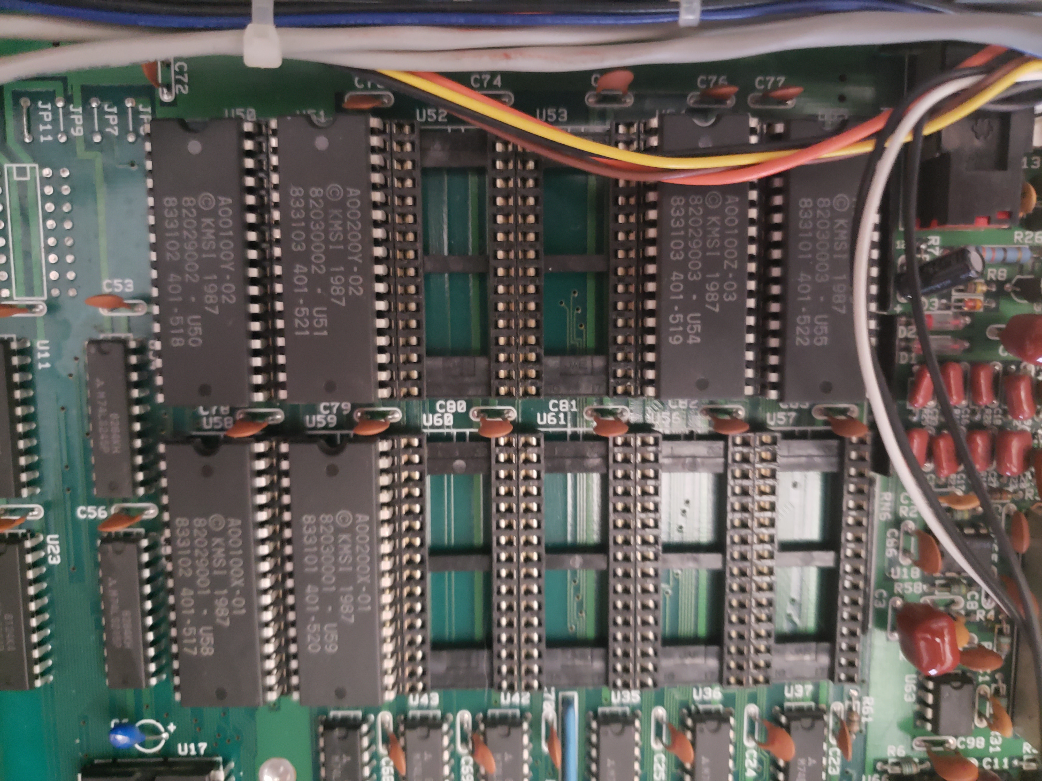
| U50 | A00100Y-02 | Sound EPROM (Stock) / Daughter Board Connection | Socket | Picture |
| U51 | A00200Y-02 | Sound EPROM (Stock) | Socket | Picture |
| U52 | [Empty] | Sound EPROM (Upgrade) | Socket | Picture |
| U53 | [Empty] | Sound EPROM (Upgrade) / Daughter Board Connection | Socket | Picture |
| U54 | A00100Z-03 | Sound EPROM (Stock) | Socket | Picture |
| U55 | A00200Z-03 | Sound EPROM (Stock) / Daughter Board Connection | Socket | Picture |
| U56 | [Empty] | Sound EPROM (Upgrade) | Socket | Picture |
| U57 | [Empty] | Sound EPROM (Upgrade) | Socket | Picture |
| U58 | A00100X-01 | Sound EPROM (Stock) | Socket | Picture |
| U59 | A00200X-01 | Sound EPROM (Stock) | Socket | Picture |
| U60 | [Empty] | Sound EPROM (Upgrade) | Socket | Picture |
| U61 | [Empty] | Sound EPROM (Upgrade) | Socket | Picture |
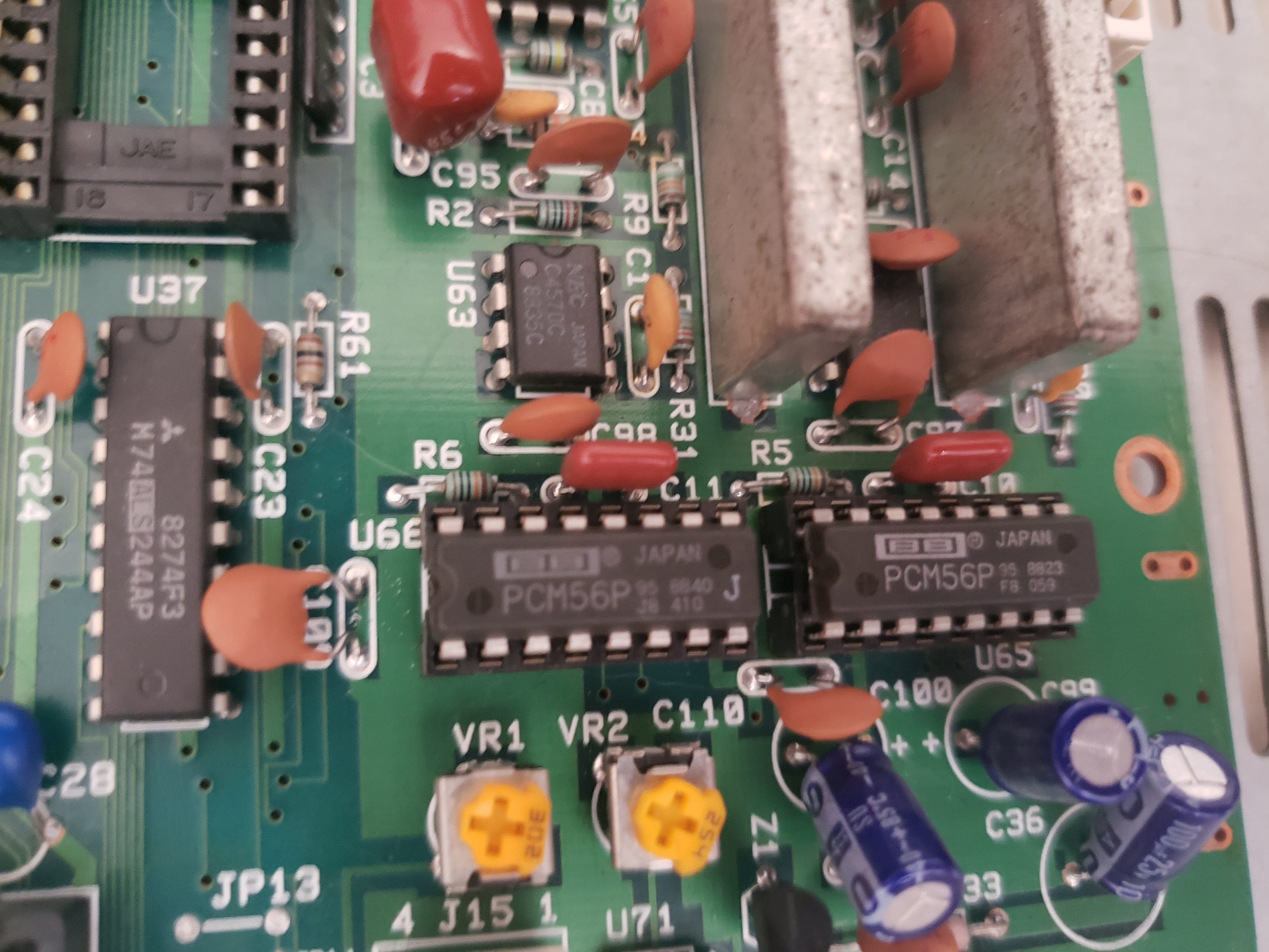
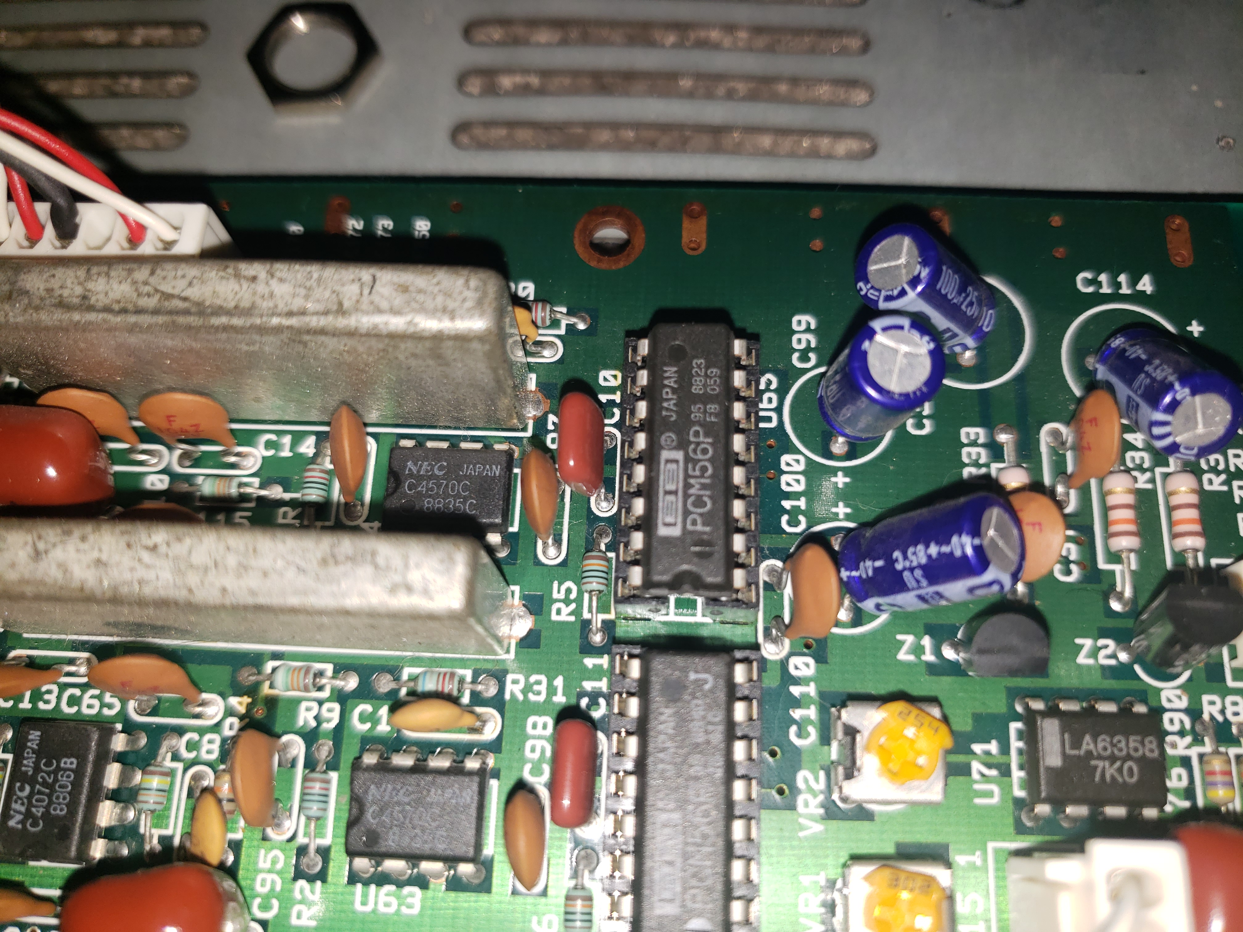
| U62 | C4570C | Dual OpAmp | Fixed | Picture |
| U63 | C4570C | Dual OpAmp | Fixed | Picture |
| U64 | M74LS74AP | Dual D-Type Positive Flip-Flops | Fixed | Picture |
| U65 | PCM56P | 16-bit DAC | Socket | Picture |
| U66 | PCM56P | 16-bit DAC | Socket | Picture |
| U67 | MC68B50P | Asynchronous Communications Interface Adaptor | Fixed | |
| U68 | M74LS367AP | Hex Bus Driver | Fixed | |
| U69 | ||||
| U70 | M74LS165AP | 8-Bit Parallel-In Serial-Out Shift Register | Fixed | Picture |
| U71 | ||||
| U72 | ||||
| U73 | ||||
| U74 | ||||
| U75 | ||||
| U76 | ||||
| U77 | ||||
| U78 | ||||
| U79 | ||||
| U80 | ||||
| U81 | ||||
| U82 | ||||
| U83 | ||||
| U84 | ||||
| U85 | ||||
| U86 | ||||
| U87 | ||||
| U88 | ||||
| U89 | ||||
| U90 | ||||
| U91 | ||||
| U92 | ||||
| U93 | ||||
| U94 | ||||
| U95 | ||||
| U96 | ||||
| U97 | ||||
| U98 | ||||
| U99 | ||||
| U100 | ||||
| U101 | ||||
| U102 | MC68B50P | Asynchronous Communications Interface Adaptor | Fixed |